
Description
“3D Line Laser Sensor | High-Precision Micron-Level Measurement for High-Speed Online Profiling and Weld Inspection”
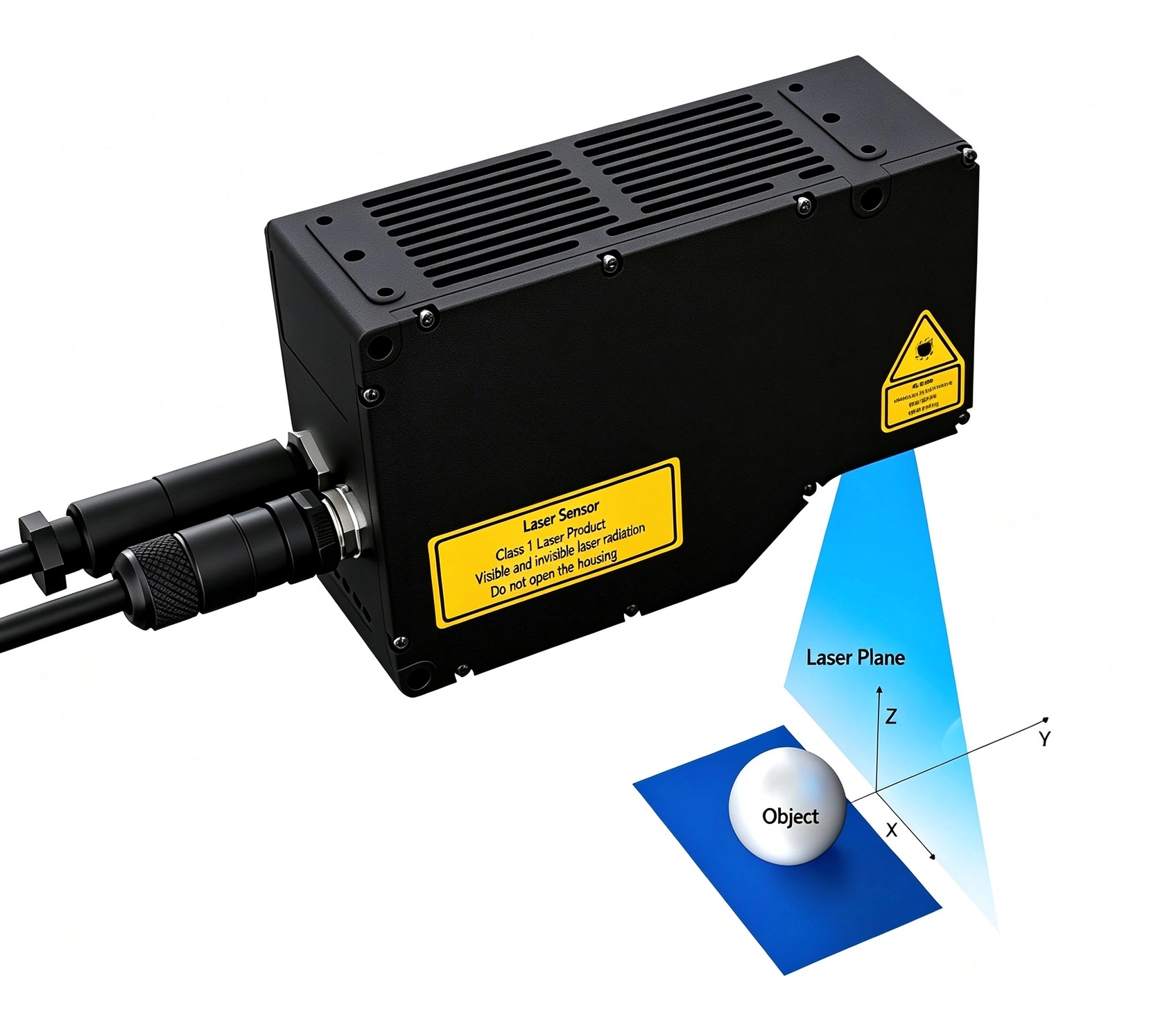
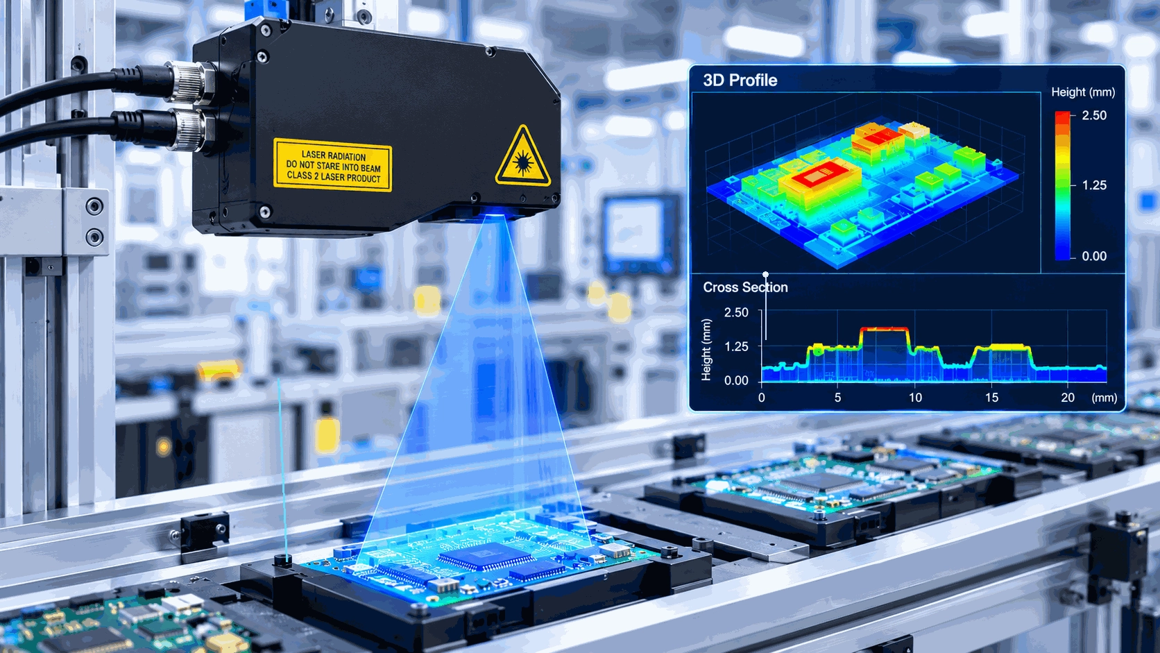
By using an image sensor to capture the laser line projected onto the surface of an object in real time, the system extracts the precise contour positions from the image. Through analysis of these contour positions, it derives the X- and Z-axis position data for each individual contour, whilst simultaneously capturing and recording the reflected brightness data at the corresponding positions. By utilising the relative motion between the object under test and the sensor, the system acquires and fuses a series of contour data points, ultimately outputting a depth map with sub-micrometre precision and a clear, sharp brightness map.
This core data constitutes the key information driving industrial vision for inspection, recognition, positioning and guidance!
It is particularly suitable for applications involving the detection and measurement of Z-axis height information, such as the measurement of product height differences, flatness, positional accuracy, contour accuracy and volume. As it is minimally affected by ambient light, it is widely used in the field of industrial inspection within smart manufacturing.
Dimensional inspection, appearance inspection, shape inspection
Resistant to the effects of colour and ambient light; simultaneously captures reflected luminance information
Not only can it detect height, width, area and volume,
but it can also perform geometric dimensional inspection and measurement
based on point, line and surface features
Utilising a single-wavelength line laser light source and
capturing 3D information via height sensing, it can reliably and clearly
detect height differences in objects of the same or different colours, whilst being largely unaffected by ambient light
By collecting reflected brightness information, it generates
clear and sharp brightness maps suitable for 2D
inspection, with height and brightness data corresponding at the pixel level
Applications of line laser 3D inspection:
Height, volume, presence/absence
Width, foreign objects, angle
Depth, burrs, orientation (front/back)
Thickness, cracks, warping
Height differences, dents, lifting
Flatness, defects, counting
| VM34xx Series | |||||||||
|---|---|---|---|---|---|---|---|---|---|
| Camera | Model | VM3406 | VM3410 | VM3415 | VM3420 | VM3422 | VM3430 | VM3440 | VM3450 | |
| Mounting Distance | Near Position(mm) | 58 | 55 | 59 | 71 | 55 | 102 | 191 | 315 |
| Reference Position(mm) | 61.5 | 59.5 | 64 | 81 | 68 | 133 | 256 | 457 | |
| Measurement Range | X-axis (Width) (mm) - FOV Near | 10 | 14 | 18 | 30 | 36 | 59 | 116 | 183 |
| X-axis (Width) (mm) - Reference Position | 10.5 | 15 | 20 | 32 | 40 | 73 | 148 | 254 | |
| X-axis (Width) (mm) - FOV Far | 11 | 16 | 21 | 36 | 48 | 97 | 204 | 416 | |
| Z-axis (Height) (mm) | 4.8 | 9 | 10.5 | 22 | 30 | 80 | 175 | 457 | |
| Profile Data | Data Point (pts) | 3200 | 3200 | 3200 | 3200 | 3200 | 3200 | 3200 | 3200 |
| Sampling Interval (μm) | 3.2 | 5 | 5.5 | 10 | 15 | 30 | 64 | 120 | |
| Repeatability Accuracy | X-axis (μm) | 0.4 | 0.5 | 0.6 | 1.2 | 1.5 | 4 | 7 | 16 |
| Z-axis (μm) | 0.1 | 0.2 | 0.3 | 0.5 | 0.6 | 1.6 | 9 | 10 | |
| Scan Rate (Hz) | 1600~30000 | 1600~30000 | 2000~30000 | 2000~30000 | 2000~30000 | 2000~30000 | 2000~30000 | 2000~30000 | |
| Z-axis Linearity (%F.S.) | ±0.01 | ±0.01 | ±0.01 | ±0.01 | ±0.01 | ±0.02 | ±0.02 | ±0.02 | |
| Mechanical | Dimensions (mm) | 126*115*57 | 126*125*59 | 112*109*57 | 135*105*57 | 112*109*57 | 115*88*57 | 175*88*54 | 195*90*54 |
| Weight (Kg) | 1.44 | 1.52 | 1.16 | 1 | 0.96 | 0.81 | 1.04 | 1.16 | |
| Light Source | Laser Wavelength (nm) | 405 | 405 | 405 | 405 | 405 | 405 | 405 | 405 |
| Output Power (mw) | 10 | 10 | 10 | 10 | 10 | 10 | 10 | 10 | |
| Laser Classes | 2M | 2M | 2M | 2M | 2M | 2M | 2M | 2M | |
| Data Output Types | Depth Map, Intensity Map, Energy Map | ||||||||
| Trigger Modes | Single-ended Trigger, Encoder Trigger, Software Trigger | ||||||||
| Power Supply (V) | 24VDC±10%@1A | 24VDC±10%@1A | 24VDC±10%@1A | 24VDC±10%@1A | 24VDC±10%@1A | 24VDC±10%@1A | 24VDC±10%@1A | 24VDC±10%@1A | |
| Enclosure Rating (IP) | IP67 | IP67 | IP67 | IP67 | IP67 | IP67 | IP67 | IP67 | |
| Environmental Resistance | Ambient Temperature (°C) | 0~50 | 0~50 | 0~50 | 0~50 | 0~50 | 0~50 | 0~50 | 0~50 |
| Ambient Humidity (%RH) | 20% to 80% RH (non-condensing) | ||||||||
| Vibration Resistance | 10 to 55 Hz, double amplitude 1.5 mm, 2 hours each in X, Y and Z directions | ||||||||
| Shock Resistance | Half-sine wave shock with 15g peak acceleration and 11ms duration | ||||||||
| Communication Interfaces | Data Interface | TCP/IP Gigabit Ethernet | |||||||
| Single-ended Input | 1 channel, 5-24V level input, available as trigger signal input | ||||||||
| Differential Input | 2 pairs, RS422, available as encoder signal input | ||||||||
| Bidirectional Differential | 2 pairs, RS485, available as array synchronization signal | ||||||||
| Notes: | |||||||||
| ① Clearance distance or reference position, where improved imaging or measurement accuracy can be achieved. | |||||||||
| ② Measurable value under nominal or extended sampling intervals. | |||||||||
| ③ Peak-to-valley deviation of X-coordinates at the intersection of the side and top edges, calculated from 4,096 profile scans of a standard quadrilateral frustum. | |||||||||
| ④ Repeatability error of average profile height measurements by scanning a standard diffuse reflection target 4,096 times at the same position. | |||||||||
| ⑤ The maximum deviation between fitted and actual measurements defines the sensor's linearity error, and the fitted measurements are plotted from the measured heights against reference heights across the measurement range. | |||||||||
| VM35xx Series | ||||||
|---|---|---|---|---|---|---|
| Camera | Model | VM3510 | VM3515 | VM3518 | VM3522 | VM3530 | |
| Mounting Distance | Near Position(mm) | 55 | 28.5 | 69.5 | 89 | 118 |
| Reference Position(mm) | 58 | 34 | 74 | 101 | 158 | |
| Measurement Range | X-axis (Width) (mm) - FOV Near | 13 | 18.5 | 25 | 40 | 63 |
| X-axis (Width) (mm) - Reference Position | 14 | 21 | 29 | 45 | 80 | |
| X-axis (Width) (mm) - FOV Far | 15 | 23 | 32 | 55 | 108 | |
| Z-axis (Height) (mm) | 6.4 | 12 | 22 | 43 | 105 | |
| Profile Data | Data Point (pts) | 4096 | 4096 | 4096 | 4096 | 4096 |
| Sampling Interval (μm) | 4 | 6 | 8 | 13 | 25 | |
| Repeatability Accuracy | X-axis (μm) | 0.5 | 0.8 | 1 | 2 | 3 |
| Z-axis (μm) | 0.2 | 0.3 | 0.4 | 0.7 | 2 | |
| Scan Rate (Hz) | 2500~56000 | 2500~56000 | 2500~56000 | 2500~56000 | 2500~56000 | |
| Z-axis Linearity (%F.S.) | ±0.01 | ±0.01 | ±0.01 | ±0.01 | ±0.02 | |
| Mechanical | Dimensions (mm) | 126*122*57 | 134*112*57 | 122*84*53 | 140*118*57 | 135*98*57 |
| Weight (Kg) | 1.22 | 1.04 | 0.8 | 1.18 | 0.92 | |
| Light Source | Laser Wavelength (nm) | 405 | 405 | 405 | 405 | 405 |
| Output Power (mw) | 10 | 10 | 10 | 10 | 10 | |
| Laser Classes | 2M | 2M | 2M | 2M | 2M | |
| Data Output Types | Depth Map, Intensity Map, Energy Map | |||||
| Trigger Modes | Single-ended Trigger, Encoder Trigger, Software Trigger | |||||
| Power Supply (V) | 24VDC±10%@1A | 24VDC±10%@1A | 24VDC±10%@1A | 24VDC±10%@1A | 24VDC±10%@1A | |
| Enclosure Rating (IP) | IP67 | IP67 | IP67 | IP67 | IP67 | |
| Environmental Resistance | Ambient Temperature (°C) | 0~50 | 0~50 | 0~50 | 0~50 | 0~50 |
| Ambient Humidity (%RH) | 20% to 80% RH (non-condensing) | |||||
| Vibration Resistance | 10 to 55 Hz, double amplitude 1.5 mm, 2 hours each in X, Y and Z directions | |||||
| Shock Resistance | Half-sine wave shock with 15g peak acceleration and 11ms duration | |||||
| Communication Interfaces | Data Interface | TCP/IP Gigabit Ethernet | ||||
| Single-ended Input | 1 channel, 5-24V level input, available as trigger signal input | |||||
| Differential Input | 2 pairs, RS422, available as encoder signal input | |||||
| Bidirectional Differential | 2 pairs, RS485, available as array synchronization signal | |||||
| Notes: | ||||||
| ① Clearance distance or reference position, where improved imaging or measurement accuracy can be achieved. | ||||||
| ② Measurable value under nominal or extended sampling intervals. | ||||||
| ③ Peak-to-valley deviation of X-coordinates at the intersection of the side and top edges, calculated from 4,096 profile scans of a standard quadrilateral frustum. | ||||||
| ④ Repeatability error of average profile height measurements by scanning a standard diffuse reflection target 4,096 times at the same position. | ||||||
| ⑤ The maximum deviation between fitted and actual measurements defines the sensor's linearity error, and the fitted measurements are plotted from the measured heights against reference heights across the measurement range. | ||||||
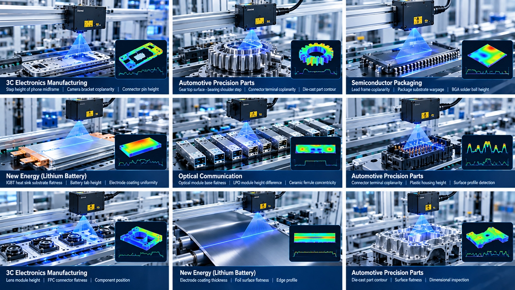
3D Laser Profiling Sensors: Industry Applications & Solutions
Discover how our high-precision 3D line laser sensors deliver reliable, sub-micron measurement and inspection across diverse advanced manufacturing sectors.
📱 3C Electronics Manufacturing
Ensure structural integrity and precise assembly in consumer electronics with high-speed 3D surface scanning:
Smartphone Middle Frames: Accurate measurement of step height differences.
Camera Brackets: Strict coplanarity and flatness inspection.
Connectors: High-precision PIN height and pitch verification.
🚗 Precision Automotive Components
Guarantee the reliability of critical automotive parts under rigorous quality standards:
Gears & Shafts: Precise measurement of the step height between the gear top surface and the bearing section.
Connectors & Terminals: Coplanarity and pitch inspection for multi-pin components.
Die-Cast Parts: Full 3D profile and contour tolerance analysis.
🔌 Semiconductor Packaging
Detect microscopic defects and surface distortions in semiconductor fabrication:
Lead Frames: Comprehensive coplanarity inspection.
Packaging Substrates: Warp and bow measurement.
BGA Solder Balls: Accurate height and coplanarity profiling.
🔋 New Energy & Lithium Batteries
Optimize the safety, performance, and dimensional stability of battery components:
IGBT Cooling Substrates: High-precision flatness measurement.
Battery Busbars & Tabs: Accurate height and connection gap inspection.
Electrode Coatings: Real-time uniformity and thickness profiling.
📡 Optical Communications
Meet the ultra-high precision demands of optical transceiver manufacturing:
Optical Module Bases: Flatness and surface contour inspection.
LPO Modules: Critical height difference and step measurement.
Ceramic Ferrules: Concentricity and outer diameter verification.
Why Choose Our 3D Line Laser Sensors?
Designed for high-speed, non-contact, and high-precision measurement, our sensors seamlessly integrate into automated production lines to eliminate defects, improve yield rates, and ensure strict quality control.
If you require other models with high-speed, high-precision FOV ranges, please contact customer services.

Reviews
There are no reviews yet.